

Please note that this guide is for a 4 pin sensor, even though the fitting location diagram for the ACV engine shows a 2 pin intercooler (location is the same though).
The 2 pin sensor is actually just a temperature sensor. The boost pressure is measured by a pipe plumbed directly to the ECU.
TERMINOLOGY
Intake manifold pressure sender / G71 sensor / MAP sensor - they're all the same thing.
FITTING LOCATIONS
Depending on which engine you have will determine the fitting location of your sensor.
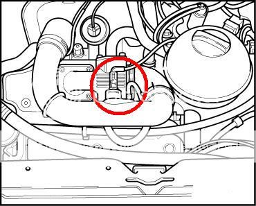
If you have an ACV engine, the sensor will be located here:
![Image]()
If you have an AJT engine, the sensor will be located here:
![Image]()
If you have an AHY, AXG or AXL engine, the sensor will be located here:
![Image]()
HOW TO TEST
With the engine not running, but the ignition switched on:
Connect up Vagcom/VCDS
Select the engine control module [01]
Select measured blocks [08]
Select Group 10
You should now be confronted with a screen similar to that below:
![Image]()
The 4 sets of figures are as follows:
1 = The amount of air being drawn into the engine. This will either be 0 or 1275 depending on the version of Vagcom/VCDS.
2 = Atmospheric pressure in millibars
3 = Intake manifold pressure in millibars
4 = This is your throttle pedal position, so should read 0 with your foot off the pedal, and 100 with your foot flat to the floor.
The values shown in 2 and 3 should be nice and stable. Value 3 should be the same as 2 (tolerance ± 30 mbar).
If everything looks good, then chances are your intake pressure sender is healthy.
If value 3 is fluctuating badly, then you need to double check the connections to the intake pressure sender, or replace it.
As a further test, you can do the following:
Start the engine
Connect up Vagcom/VCDS
Select the engine control module [01]
Select measured blocks [08]
Select Group 10
With the engine idling, disconnect the intake manifold pressure sender connector and watch value 3. It must fall briefly to about 400 mbar and then rise to the same value as value 2.
If it doesn’t, check the connections to the intake pressure sender, or replace it.
The 2 pin sensor is actually just a temperature sensor. The boost pressure is measured by a pipe plumbed directly to the ECU.
TERMINOLOGY
Intake manifold pressure sender / G71 sensor / MAP sensor - they're all the same thing.
FITTING LOCATIONS
Depending on which engine you have will determine the fitting location of your sensor.
If you have an ACV engine, the sensor will be located here:

If you have an AJT engine, the sensor will be located here:
If you have an AHY, AXG or AXL engine, the sensor will be located here:

HOW TO TEST
With the engine not running, but the ignition switched on:
Connect up Vagcom/VCDS
Select the engine control module [01]
Select measured blocks [08]
Select Group 10
You should now be confronted with a screen similar to that below:

The 4 sets of figures are as follows:
1 = The amount of air being drawn into the engine. This will either be 0 or 1275 depending on the version of Vagcom/VCDS.
2 = Atmospheric pressure in millibars
3 = Intake manifold pressure in millibars
4 = This is your throttle pedal position, so should read 0 with your foot off the pedal, and 100 with your foot flat to the floor.
The values shown in 2 and 3 should be nice and stable. Value 3 should be the same as 2 (tolerance ± 30 mbar).
If everything looks good, then chances are your intake pressure sender is healthy.
If value 3 is fluctuating badly, then you need to double check the connections to the intake pressure sender, or replace it.
As a further test, you can do the following:
Start the engine
Connect up Vagcom/VCDS
Select the engine control module [01]
Select measured blocks [08]
Select Group 10
With the engine idling, disconnect the intake manifold pressure sender connector and watch value 3. It must fall briefly to about 400 mbar and then rise to the same value as value 2.
If it doesn’t, check the connections to the intake pressure sender, or replace it.
 .
.

