VW T4 Forum - VW T5 Forum banner

T5/1.9tdi Cam Position sensor voltage (at Pin 1?)

14K views 10 replies 4 participants last post by  JamesF_T5  
#1 ·
Hi any wise sages... On Cam Position issues.
Delayed cranking problem..
Have fitted a new GPS but no change.
On checking the connector pins I have :
Pin 1: 4.8v (should this be 12v?)
Pin 2: 4.9v (which I ssume is correct)
Pin 3: 0v (0.7ohms continuity so is Earth)

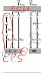
I've attached wiring diagram but doesn't confirm In is 12v, but I suspect it should be, but I can't ID it's source to check continuity back to pin 1 (ref: T6/q1 Black/Green wire.) .. But where is T6 plug?
Any help appreciated.
James.
 

Attachments

#2 ·
Can't help with solving the problem, but...
The crank position sensor will be generating a pulse output so DC measurements are not that helpful. You need to look at the signal on a scope.
5V is a common voltage for digital circuits so it's not impossible for this not to be 12V.
Quick search for crank position waveforms came up with this. Any use?
 
#3 ·
Hi. Thanks for your response. I was hoping there was no correlation between the crank v cam sensor on this, but as you suggest, a scope view is the only sure way to attempt to trace what is going on here. I will need to get someone with a Magic box of tricks to look further at it,
I have been going dizzy looking at supply and signal dc voltage to the CPS which as always are contradictory from different sources, though a couple do pinpoint a 12v supply voltage to Pin 1.but will get a Auto Elect with Scope to look at it.
Thanks again.
James.
 
#4 · (Edited)
I've just noticed on your other thread that you said the engine was rebuilt. Has the problem been since then? If so, there are two cam sensors for the 1.9. We had this come up a while ago and the only reliable way to tell is to check by engine number at the dealer or using 7zap or similar. If the sensor doesn't match the engine code, the hall sensor will be in the wrong place and then will be misread by the ECU.

As aferris2 says you can't check the signal from the cam sensor without a scope because the pulse is too fast to be seen by a multimeter but if you have access to VCDS there is a block that shows what the result of that pulse is. If there is no pulse, no figures will show in that block, if it is pulse signal is corrupted, the numbers won't show the expected half crankshaft speed, but instead the wrong speed or jumping around. Sometimes with your your long cranking fault, a correlation code (between cam and crank signals) will also be present.

If you don't have access to genuine VCDS you might be able to check these things with a cheap code reader because it only requires reading fault codes and seeing live data from the sensors which most of the reasonable ones seem to be able to manage.

The block you need should be labelled 'camshaft speed'. I don't know the number on the 1.9 but on my 2.5 I can see it at group 51 field 2. From my van - 051,2,Camshaft Speed,(G40),Specification: Half Engine Speed ±50 RPM/min

Otherwise a search around using terms VCDS - Ross-Tech- cam sensor block number or similar should find it. Good luck! :)

Edit- Just found one of the threads I was on about. I posted a pic of the VCDS screen and cam sensor readings on a 1.9 Golf but it looks like the diesels all use the same group and individual block. Starting issue
 
#5 ·
Hi and thanks for your comprehensive reply.
After. I obtained the van, the engine was only (briefly) started a couple of times to confirm it's obvious clattering of Mains bearing and Pistons slapping the bores.. So was quickly shut off, but it was a very long crankibg time, which probably wronly was maybe at that point put down to the poor state of the ENGINE.
(1. 9 / 102 BRS Engine) internals but... Was likely Cam Sensor related also.
As it was still noted to hve a delayed start / long crank on its first start ups after the rebuild, I fitted a new Cam Posn Sensor then in the hope it would be an obvious fix. I think this was a Febi Bilstein Sensor (from EuroCar Parts). It would be interesting to know if the Can Sensor I fitted and indeed the old one were both not compatible for a BRS engine...?!

Your detailed points makes some sense but I'll be honest am not that tek savvy for fully understanding the scope pulse, waves, blocks correlations, but do appreciate the synchonization has to align at the proscribed intervals in order to achieve the successful ignition nd running parameters required by the ECU inputs and needs.
As a Humble home/Driveway mechanic, I don't have access to VCDS, I have a small hand held Autel Code Reader so will see if any live date on that resembles your points.
I will try source the Ross-Tech Sensor article.
Thank you.
I will gladly update if manage to rectify this issue which is very frustrating..
Regards
James.
 
#6 ·
Interesting that yours is a BRS. Within that thread I linked to is yet another link which shows that both the cam sensor and the trigger plate are specific to the different engine codes. Look out for post #27 by Hellhounds where he lists which trigger plate and which sensor part number should go with which engine. And someone else kindly posts pictures of the two different trigger plates.

It's worth confirming that both of these parts are correct on your engine before you move on. If either part is wrong it will cause long cranking because the ECU will think the cam and crank are out of time with each other and then use only the crank sensor to keep the engine running, so there will be a slight delay on starting as it works it all out.
 
#9 ·
Hi. Thanks for that.
I'll check with the engineer who rebuilt. It, bit I assume that the same trigger plate would have been fitted on rebuild.
it's probably confirmed by the problem existing prior to and after the rebuild, whether the fault is either on the engine, ancils or within the van's wiring.
Just annoying it's not just simply fixed by replacing the Cam Sensor.